A Scalable, Commodity Data Center Network Architecture
0x00 引言
这篇Paper是数据中心网络设计上很重要的一篇。这里一个核心的概念就是Clos Networks和Fat-Trees。
Specifically, one instance of our architecture employs 48-port Ethernet switches capable of providing full bandwidth to up 27,648 hosts. By leveraging strictly commodity switches, we achieve lower cost than existing solutions while simultaneously delivering more bandwidth. Our solution requires no changes to end hosts, is fully TCP/IP compatible, and imposes only moderate modifications to the forwarding functions of the switches themselves.
0x01 基本架构
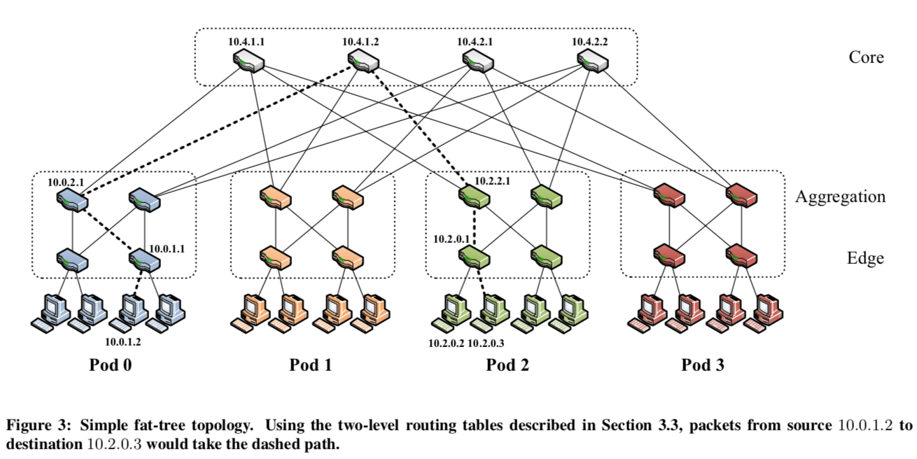
下面的图是一个k叉的fat-tree的topology。设交换机的端口数量为k,核心交换机的数量为(k/2)^2,pods的数量数k,在下面的图中的接近正方形的矩形的虚线框就是一个pod。每一个核心交换机都和每一个pod相连接。在一个pod里面,存在的交换机分为2层,下面的一层的一半的端口连接主机,一半的端口连接上一层的交换机,上一层(aggregation layerz)的交换机连接k/2个核心交换机。这里假设端口为k,则: \(\\ PODs的数量为k,Aggregation的交换机为k/2, Edge的交换机为k/2,则可以支持的hosts的数量为 \frac{k^{3}}{4}. \\ 在论文的假设k = 48, 则N = 27648.\) 在端口数量为k的情况下,有上面的计算可知支持的hosts的数量的27648。支持的子网的数量为1,152。每个子网24台主机,即端口数量的一半。在不同pods里面的主机存在576条((k/2)^2)不同联通的线路。
0x03 Two-Level Routing Table
这个数据中心网络的设计要求多route table做一些修改。这里前面已经提到pods之间主机是存在很多条连接的线路的。如果使用原有的部分,就只会使用其中很少的一部分。另外的一个问题就是诸多的子网会要求很多的子网前缀,每一个lower-level pod switch需要k/2个(对每个其它的子网,可以从k/2个方向走),总共就需要k*(k/2)^2个。数量会随着k的增长而飞速增长。这里使用的IP地址为10.0.0.0/8的地址块。对于pod switch而言,地址的编码形式是10.pod.switch.1(pod \in [0, k-1], switch \in [0, k − 1],从左到右,从下到上分配)。对于核心交换机,分配的地址是10.k.j.i。j,i代表在(k/2)^2的网格里面的坐标。对于主机而言,分配的地址是10.pod.switch.ID(ID \in [2, k/2+1])。
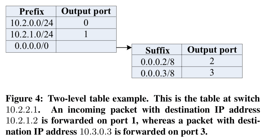
为了解决传统的路由的方式不能充分利用这里的网络topology的问题,这里使用了Two-Level 的路由表的方式。在主的路由表里面的一项,有可能存在一个额外的指针指向另外一个小的次级的表,这个表的基本项结构是(suffix, port)。这里很明显的特点就是这里使用的是后缀,而传统的路由使用的都是前缀。这里这样做的原因就是可以使得传输到一个字网里面不同主机的流量走不同的线路。
Whereas entries in the primary table are left-handed (i.e., /m prefix masks of the form 1^m * 0^(32−m) ), entries in the secondary tables are right-handed (i.e. /m suffix masks of the form 0^(32−m)*1^m ). If the longest-matching prefix search yields a non-terminating prefix, then the longest-matching suffix in the secondary table is found and used.
这样做的一个可能的缺点就是增加路由的延时,但是Paper中认为这个延时是微不足道的。
0x04 Routing Algorithm
-
Pod Switches, 在一个pod里面,交换机对应的prefixs是terminating prefixes,也就是说不会根据upper-layer的交换机会直接将数据包交给对应的lowe layer的交换机,这样即可。在不同的pod之间通信时,交换机拥有的前是/0,这样会在次级的路由表里面找到对应的一项,这样的好处就是可以通过host-ID来将流量均匀分配。同时,一对主机之间的通信理论走的是相同的路线,这样可以有效的避免packet重排序。对于lower layer的交换机,会忽略分配/24前缀的路由项。下面的伪代码就表示了upper layer交换机中路由表项分配的基本方式,咸鱼添加了一些注释:
foreach pod x in [0,k−1] do // 下面分配了[(k/2), k − 1],在lower layer中的交换机才是没有下面得subnet的循环的 // 这样lowe layer的交换机向upper layer转发数据包的时候只会根据host的ID来。 foreach switch z in [(k/2), k − 1] do foreach subnet i in [0, (k/2) − 1] do addPrefix(10.x.z.1, 10.x.i.0/24, i); end addPrefix(10.x.z.1, 0.0.0.0/0, 0); foreach host ID i in [2, (k/2) + 1] do addSuffix(10.x.z.1, 0.0.0.i/8, (i − 2 + z)mod(k/2) + (k/2)); end end end -
Core Switches, 核心交换机只会包含/16形式的terminating prefixes,会将对应的数据包路由到指定的pod。下面的伪代码就表示了分配的基本方式,这里的方式就比上面的简单很多:
foreach j in [1, (k/2)] do
	foreach i in [1, (k/2)] do
		foreach destination pod x in [0, (k/2) − 1] do
			addPrefix(10.k.j.i,10.x.0.0/16, x);
		end
	end
end
举个例子:一个数据包从原地址10.0.1.2出发,目的是 10.2.0.3,在上面的架构图中有表示:
- 首先交给low layer的交换机,这里是10.0.1.1。这个交换机和源主机直接相连;
- 由于源IP的后缀是2, 根据路由表,数据包会被转发到upper layer的交换机10.0.2.1;
- 这里10.0.2.1得交换机做的的动作和lowe layer的相同,数据包被转发给了10.4.1.2;
- 核心交换机工具10.2.0.0/16 prefix来转发数据包,这里被转发给了10.2.2.1;
- 对于10.2.2.1而言,这个数据的目的在同一个pod里面,所以这里是terminating prefix, 10.2.0.0/24,会根据前缀来转发给10.2.0.1,
- 10.2.0.1将数据包转发给目的主机。
Note that for simultaneous communication from 10.0.1.3 to another host 10.2.0.2, traditional single-path IP routing would follow the same path as the flow above because both destinations are on the same subnet. Unfortunately, this would eliminate all of the fan-out benefits of the fat-tree topology. Instead, our two-level table lookup allows switch 10.0.1.1 to forward the second flow to 10.0.3.1 based on right-handed matching in the two-level table.
0x05 Flow Classification & Flow Scheduling
这里将的主要是如果利用识别流的类型和对这些流进行调度,这样可以获得减少局部的阻塞等的好处。Pod的交换机可以这样做:
pod switches:
1. Recognize subsequent packets of the same flow, and forward them on the same outgoing port.

2. Periodically reassign a minimal number of flow output ports to minimize any disparity between the aggregate flow capacity of different ports.
基本思路就是周期性的流量重新分配来解决问题。对于流的调度来说,这个是一个比较大的话题,在这篇论文发表之后(2008)出现了很多关于这个得文章,不过咸鱼美看过几篇,不是很了解。Paper中说明的方法是一个中心化的方法,一种中心的scheduler来知道系统的整体的情况,由它来作出调度的选择。
-
Edge Switches,Edge交换机的做法就是发现一个出的流的流量达到一个阈值的时候,将这个信息通知给中心scheduler,这也可以是一个重新分配这个流发送通道的一个请求。这样的话交换机是不能决定如何分配这个流的,中心的scheduler才有这个权限;
-
Central Scheduler,中下的Scheduler是可以存在副本的。它追踪所有的活跃的大的流并尝试将其分配到冲突更少的路径上面。当Scheduler接收到一个新的流的通知的时候,它会扫描核心交换机,在可以的路线中发现没有被预留的。并将这个流线标记为预留的,然后将相关的信息通知upper layer和lower layer的交换机,这样它们就可以根据这个信息来作出转发的决策了。此外,
A similar search is performed for intra-pod large flows; this time for an uncontended path through an upper-layer pod switch. The scheduler garbage collects flows whose last update is older than a given time, clearing their reservations. Note that the edge switches do not block and wait for the scheduler to perform this computation, but initially treat a large flow like any other.
0x06 Fault-Tolerance
由于一对主机之间诸多的通信路线的存在,给了Fault-Tolerance设计很大的方便。这里使用一种广播的方式来通知链路or交换机的故障。在这种模式中,每个交换机和它相邻的交换机保持了双向转发检测会话(Bidirectional Forwarding Detection session (BFD)),以确定链接或相邻交换机何时出现故障。这里可以容忍两类错误,1. 一个是一个pod之类的lower和 upper layer交换机之间的故障,2. 二个是upper layer和核心交换机之间的故障。对于lowe layer的交换机故障,会直接导致一些主机的网络变得不可用,可以使用的解决办法就是使用冗余的交换机。Paper中这里关于故障还有更加详细的讨论[1].
0x07 评估
详细信息参考[1].
参考
- A Scalable, Commodity Data Center Network Architecture, SIGCOMM’08.
- https://en.wikipedia.org/wiki/Clos_network, 维基百科.